
Pulse Control 2 Phase Closed Loop Stepper Drive T42
Pulse Control 2 Phase Closed Loop Stepper Drive T42 Overview
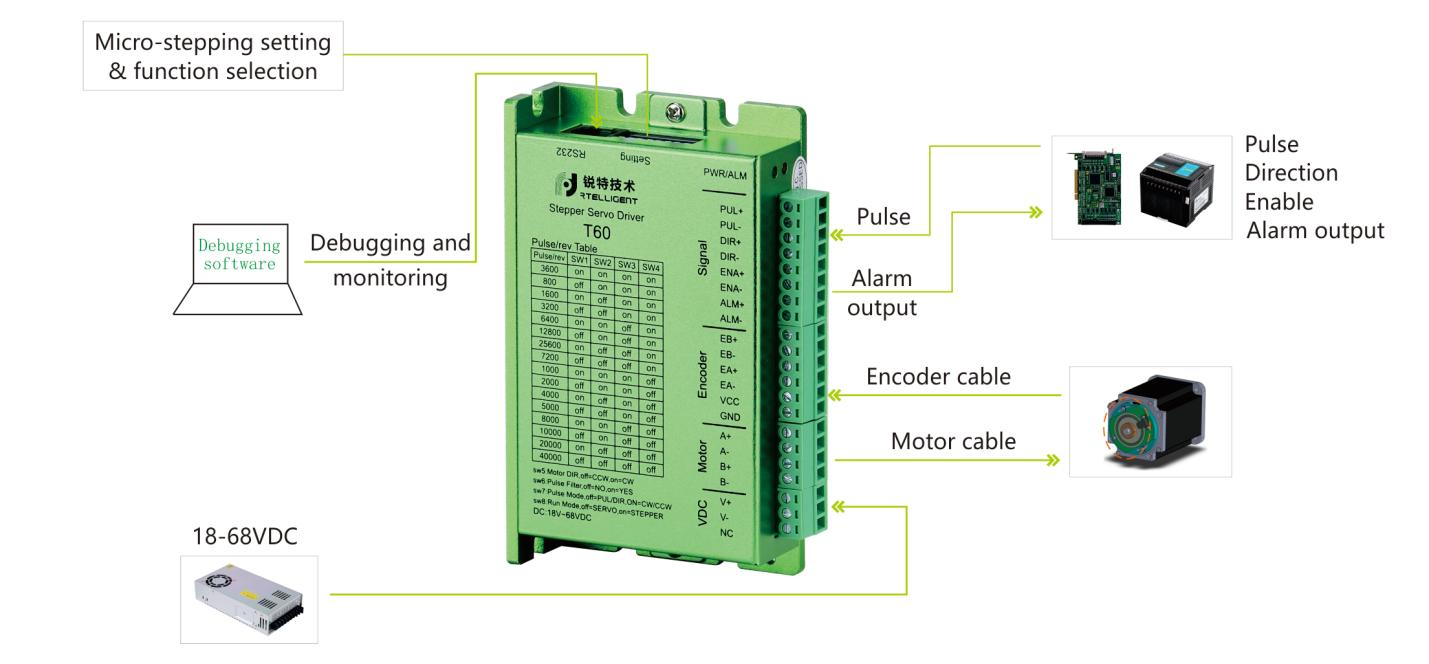
T60/T42 closed loop stepper drive, based on 32-bit DSP platform, built-in vector control technology and servo demodulation function, combined with the feedback of closed-loop motor encoder, makes the closed loop stepper system has the characteristics of low noise, low heat, no loss of step and higher application speed, which can improve the performance of intelligent equipment system in all aspects.
T60 matches closed- loop stepper motors below 60mm, and T42 matches closed- loop stepper motors below 42mm.
- Pulse Mode: PUL&DIR/CW&CCW
- Signal Level: 3.3-24V compatible; serial resistance not required for the application of PLC.
- Power Voltage: 18-68VDC, and 36 or 48V recommended.
- Typical applications: Auto-screwdriving machine, servo dispenser, wire-stripping machine, labeling machine, medical detector
- electronic assembly equipment etc


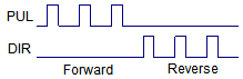
Pulse Mode
The standard T series driver signal interface is in the form of pulse, and T60 can receive two kinds of pulse command signals.
Pulse and direction (PUL + DIR)
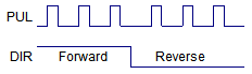
Double pulse (CW +CCW)
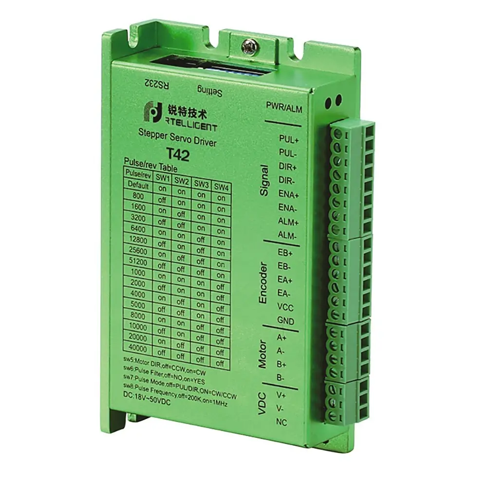
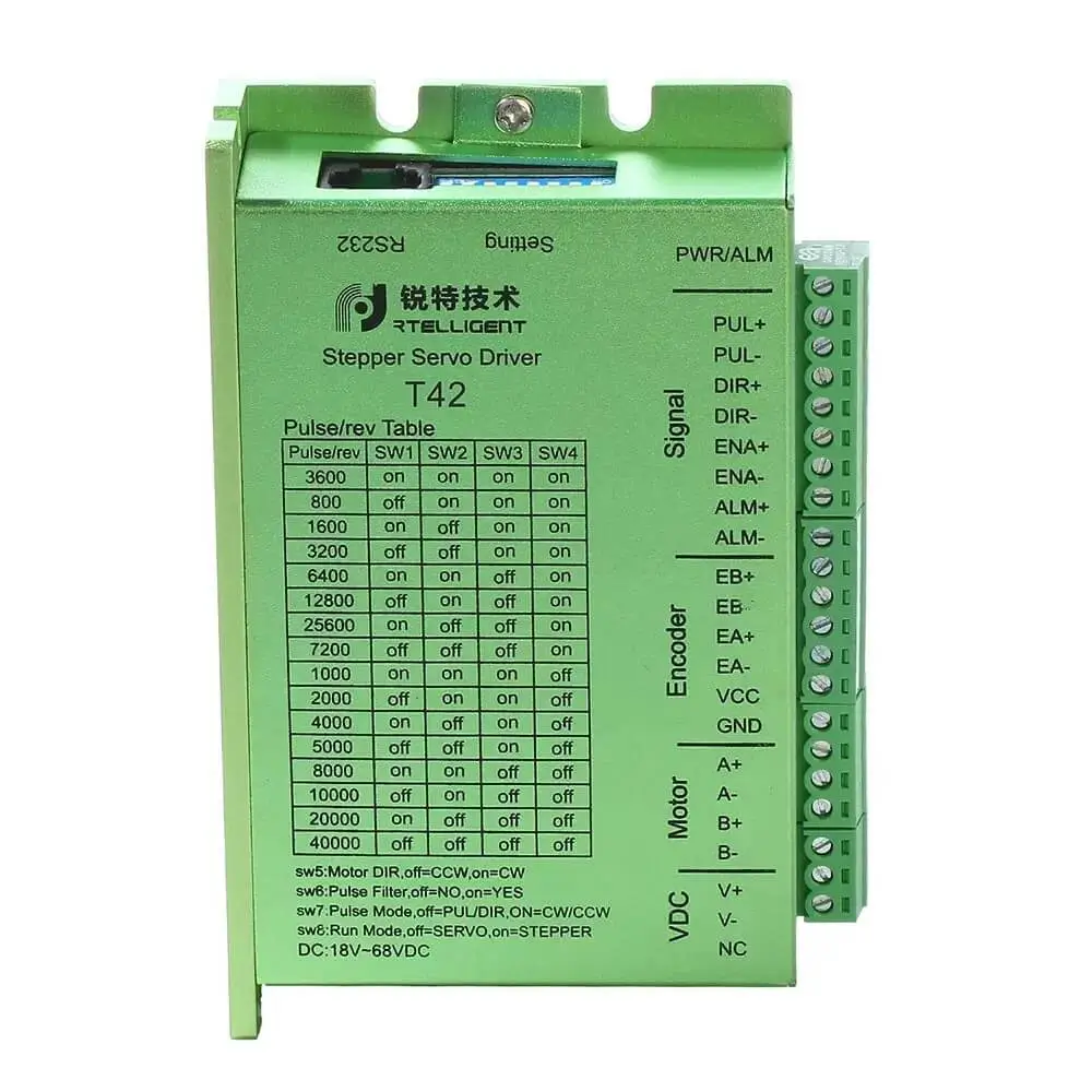
Micro-stepping Setting
| Pulse/rev | SW1 | SW2 | SW3 | SW4 | Remarks |
|---|---|---|---|---|---|
| 3600 | on | on | on | on | The DIP switch is turned to the “3600” state and the testing software can freely change other subdivisions. |
| 800 | off | on | on | on | |
| 1600 | on | off | on | on | |
| 3200 | off | off | on | on | |
| 6400 | on | on | off | on | |
| 12800 | off | on | off | on | |
| 25600 | on | off | off | on | |
| 7200 | off | off | off | on | |
| 1000 | on | on | on | off | |
| 2000 | off | on | on | off | |
| 4000 | on | off | on | off | |
| 5000 | off | off | on | off | |
| 8000 | on | on | off | off | |
| 10000 | off | on | off | off | |
| 20000 | on | off | off | off | |
| 40000 | off | off | off | off |
| Power supply | 18–68 VDC |
|---|---|
| Control precision | 4000 Pulse/r |
| Pulse mode | Direction & pulse, CW/CCW double pulse |
| Current control | Servo vector control algorithm |
| Micro-stepping settings | DIP switch settings, 15 options (or debugging software settings) |
| Speed range | Conventional 1200 ~ 1500 rpm, up to 4000 rpm |
| Resonance suppression | Automatically calculate the resonance point and inhibit the IF vibration |
| PID parameter adjustment | Test software to adjust motor PID characteristics |
| Pulse filtering | 2MHz digital signal filter |
| Alarm output | Alarm output of over-current, over-voltage, position error, etc |

Inquiry Now
Scan the QR to call
Submit Inquiry for
×